Errore nel formato dell'e-mail
emailCannotEmpty
emailDoesExist
pwdLetterLimtTip
inconsistentPwd
pwdLetterLimtTip
inconsistentPwd

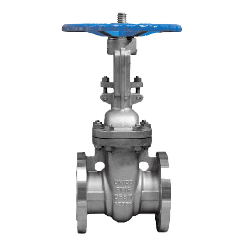
F4 DIN GATE VALVE
ETM FIG. FIG.F.163
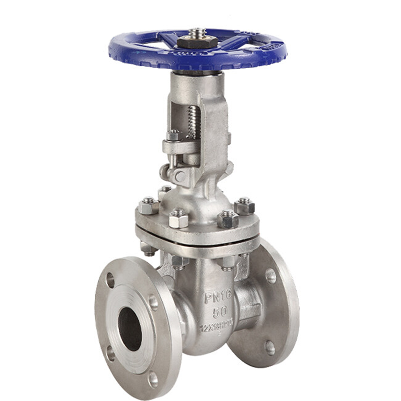
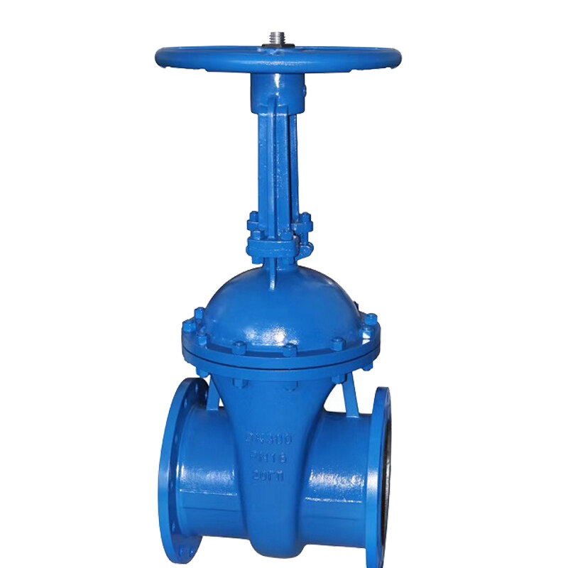
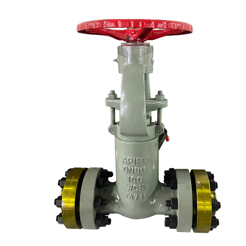
DIN Bolted Bonnet F7 Gate Valves
Gate Valve / Feature:
Proven technology
Full range of body/bonnet & trim materials Choice of solid, flexible or split wedge design
Welded seat in stellite or Cr-steel
Back seating design
Upset forged T-head stem design OS&Y construction
Full port design Full length wedge guides
Optional impact hand wheel
Optional lengthen stem
DIN PN:PN16,PN25,PN40,PN63,PN100,PN160,PN250,PN320
DIN DN:DN40-DN1200
Temperature Rating:-260°C up to +450°C
Body forms: DIN3202-F4,DIN3202-F5,DIN3202-F7
Basic shell material:Low temperature carbon steel, Carbon steel, High temperature carbon steel, Stainless steel, High temperature stainless steel, High chromium stainless steel, Hastelloy, Inconel, Pure nickel, Titanium, Other special alloys
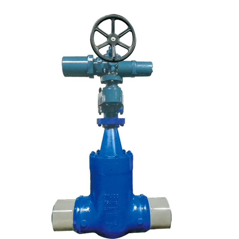
Connections:Flanged ends, Butt welding ends
Operation:Handwheel, Lever, Chainwheel, Gear operator, Pneumatic piston actuator, Pneumatic diaphragm actuator, Electric actuator
Gate Valve / Applications: Industry, power stations , flue gas purification plant, processing technology, gas supply, vapour facilities, recycling facilities, vacuum facilities, hot water, heating technology, district heating, thermal oil applications, general plant manufacturing, etc.
Gate Valve / Mediums: Steam,gases, hot water, thermal oil, process water, vacuum facilities, ammonia etc.
Stanrard material : GP240GH (1.0619/GS-C25),G-X6CrNi18.9(1.4308),G-X6CrNiMo18.10 (1.4408)
Design&manufacture standard conforms to EN1984
Face to face standard conforms to EN558-1
Flange standard conforms to EN1092-1
Test conforms to EN12266
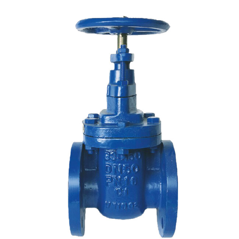
Metals Valve’s DIN 3352 gate valves are typical wedge gate valves designed and manufactured to German DIN standards covering materials of cast iron, cast steel, stainless steel and alloy steel. The housing connection between body and bonnet can be classified as restrained or unrestrained flange seal, pressure self-sealing, and screwed seal. DIN 3352 gate valves can be manufactured either with rising stem(OS&Y) or non-rising stem. Rigid wedge and resilient wedge are available upon clients’ request.
Operation: Handwheel, Worm Gear, Electric Actuator, Pneumatic Actuactor. End Connections: Flanged(RF, FF, or RTJ), Butt Weld(BW). Standards: designed & manufactured to DIN 3352; inspected and tested to DIN 3230, ISO 5208, EN 12266; flanged ends to EN 1092-1, DIN 2543~DIN 2550; butt welding ends to DIN 3239/ EN 12627; face to face length: DIN 3202, EN 588-1, ISO 5752. Pressure Ratings: PN10, PN16, PN25, PN60; Applications: oil & gas, sewage treatment, water supply, chemical projects.
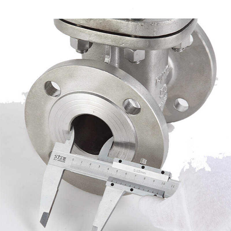
Flange End: EN1092-1
Test & Inspection: EN12266-1/2
Design Feature
-Full Bore Design
-Superior flow rates & small friction loss
-Low torque value for closing and opening the valve
-Flexible wedge for better seating and ease of operation
-Smooth finish and superior sealing for seat face
-Every valve is manufactured with specific number on body for traceability
Quick Detail
|
Type |
Gate Valve |
|
Size |
DN15-DN600 |
|
Pressure |
PN 16 |
|
Construction |
Bolted Bonnet, Rising Stem, Outside Screw and Yoke |
|
Connection |
Flange Connection |
|
Operation |
Handwheel |
|
Body Material |
Stainless Steel CF8M |
|
TrimMaterial |
Stainless Steel |
|
Temperature Range |
-268℃~+648℃ |
|
Medium |
Water, Oil and Gas |
|
Origin |
China |
- Drawing and Material Selection for DIN 3352 gate valves
Section Drawing
Material Selection
|
Application |
|||
|
Hot oil system, steam system, hot and cold water system etc. |
|||
|
Advantage |
|||
|
1.Bellow seal element. The key part of bellow sealed globe valves is metal bellow. It is the connection between cover and stem with automatic roll welding. The metal bellow can keep the stem part no leakage. |
|||
|
2.Benefit from the con and streamline shape design, the disc has a reliable seal and longer service life. |
|||
|
3.Double seal design(bellows+packing). Bellow and packing can protect against leakage and provide a excellent seal. |
|||
|
4.Grease nipple. It can direct lubricate the stem, nut and sleeve. |
|||
|
5.Ergonomic hand wheel. It provide longer service life and easier operation. |
|||
|
Technical specification |
|||
|
Design standard: DIN 3356 |
|||
|
Face to face dimension: DIN 3202 |
|||
|
Flanged ends: DIN 2543-2545 |
|||
|
Test & inspection: DIN 3230 |
|||
|
Nominal Pressure |
PN |
|
|
|
Test Pressure |
Strength test |
1.5PN |
MPa |
|
Sealing test |
1.1PN |
||
|
Gas seal test |
0.6 |
||
|
-- |
-- |
||
|
Suitable temp |
-196℃~600℃ |
||
|
NO. |
Part name |
Material |
|
1 |
Body |
GS-C25、1.4301、1.4401 |
|
2 |
Disc |
GS-C25+1.4201/1.4301 |
|
3 |
Seat |
1.4301 、Stellite |
|
4 |
Stem |
1.4021、1.4301、1.4401 |
|
5 |
Double-headed bolt |
ASTM 193-B7、A193-B8 |
|
6 |
Nut |
ASTM 194-2H、A194-8 |
|
7 |
Metal gasket |
Stainless steel |
|
8 |
Back seal |
1.4021、1.4301 |
|
9 |
Nut |
ASTM 194-2H、A194-8 |
|
10 |
Cover |
GS-C25、1.4301、1.4401 |
|
11 |
Packing |
Flexible graphite |
|
12 |
Gland |
GS-C25、1.4301 |
|
13 |
Nut |
ASTM 194-2H、A194-8 |
|
14 |
Jack bolt |
ASTM 193-B7、A193-B8 |
|
15 |
Stem nut |
Copper alloy、D2、BL2 |
|
16 |
Oil cup |
Assemble |
|
17 |
Cap |
1C45、1.4301、1.4401 |
|
18 |
Hand wheel |
Carbon steel |
|
PN 16 - F4 |
||||||||
|
DN |
Main connection size |
|||||||
|
L |
D |
D1 |
D2 |
b |
f |
H |
n-Φd |
|
|
40 |
140 |
150 |
110 |
88 |
18 |
3 |
305 |
4-Φ18 |
|
50 |
150 |
165 |
125 |
102 |
20 |
3 |
344 |
4-Φ18 |
|
65 |
170 |
185 |
145 |
122 |
20 |
3 |
377 |
4-Φ18 |
|
80 |
180 |
200 |
160 |
138 |
20 |
3 |
415 |
8-Φ18 |
|
100 |
190 |
220 |
180 |
158 |
20 |
3 |
473 |
8-Φ18 |
|
125 |
200 |
250 |
210 |
188 |
22 |
3 |
505 |
8-Φ18 |
|
150 |
210 |
285 |
240 |
212 |
22 |
3 |
550 |
8-Φ22 |
|
200 |
230 |
340 |
295 |
268 |
24 |
3 |
815 |
12-Φ22 |
|
250 |
250 |
405 |
355 |
320 |
26 |
3 |
969 |
12-Φ26 |
|
300 |
270 |
460 |
410 |
378 |
28 |
4 |
1145 |
12-Φ26 |
|
PN 25 - F5 |
||||||||
|
50 |
250 |
165 |
125 |
102 |
20 |
3 |
344 |
4-Φ18 |
|
65 |
270 |
185 |
145 |
122 |
22 |
3 |
377 |
8-Φ18 |
|
80 |
280 |
200 |
160 |
138 |
24 |
3 |
415 |
8-Φ18 |
|
100 |
300 |
235 |
190 |
162 |
24 |
3 |
473 |
8-Φ22 |
|
125 |
325 |
270 |
220 |
188 |
26 |
3 |
505 |
8-Φ26 |
|
150 |
350 |
300 |
250 |
218 |
28 |
3 |
550 |
8-Φ26 |
|
200 |
400 |
360 |
310 |
278 |
30 |
3 |
815 |
12-Φ26 |
|
250 |
450 |
425 |
370 |
335 |
32 |
3 |
969 |
12-Φ30 |
|
300 |
500 |
485 |
430 |
395 |
34 |
4 |
1145 |
16-Φ30 |
|
350 |
550 |
555 |
490 |
450 |
38 |
4 |
1300 |
16-Φ33 |
|
400 |
600 |
620 |
550 |
505 |
40 |
4 |
1450 |
16-Φ36 |
|
450 |
650 |
670 |
600 |
548 |
42 |
4 |
1597 |
20-Φ36 |
|
500 |
700 |
730 |
660 |
566 |
44 |
4 |
1755 |
20-Φ36 |
|
600 |
800 |
845 |
770 |
670 |
46 |
5 |
1985 |
20-Φ39 |
|
PN 40 - F7 |
||||||||
|
50 |
250 |
165 |
125 |
102 |
20 |
3 |
344 |
4-Φ18 |
|
65 |
290 |
185 |
145 |
122 |
22 |
3 |
377 |
8-Φ18 |
|
80 |
310 |
200 |
160 |
138 |
24 |
3 |
415 |
8-Φ18 |
|
100 |
350 |
235 |
190 |
162 |
24 |
3 |
473 |
8-Φ22 |
|
125 |
400 |
270 |
220 |
188 |
26 |
3 |
505 |
8-Φ26 |
|
150 |
450 |
300 |
250 |
218 |
28 |
3 |
550 |
8-Φ26 |
|
200 |
550 |
375 |
320 |
285 |
34 |
3 |
815 |
12-Φ30 |
|
250 |
650 |
450 |
385 |
345 |
38 |
3 |
969 |
12-Φ33 |
|
300 |
750 |
515 |
450 |
410 |
42 |
4 |
1145 |
16-Φ33 |
